Friday, June 09, 2006

The Garage - Project Intro and Material Delivery


For the next while my focus will be shifting from vehicles to their stable.... My garage is in desparate need of an "Extreme Makeover".

After much debate and penny pinching, we bit the bullet and purchased the materials we will need to rebuild the garage. The "Extreme Makeover" will consist of the following:

-strengthening of existing roof by modifying to a trussed style full-span structure
-replacement of bottom 2 feet of roof sheathing
-removal of old shingles, new shingles installed
-construction of new 2x4 framed walls on 3 sides, 2x6 wall on front, inside existing structure, tied to new roof structure
-removal of existing walls
-"smart panel" siding on all four walls
-16 foot insulated steel garage door
-32" insulated steel entry door on side of garage
-framing for windows in future
-65' "good neighbour" style fence down LHS of property line
-eventual new wiring, fuse box, lighting, insulation, inside OSB, air lines, paint, etc...

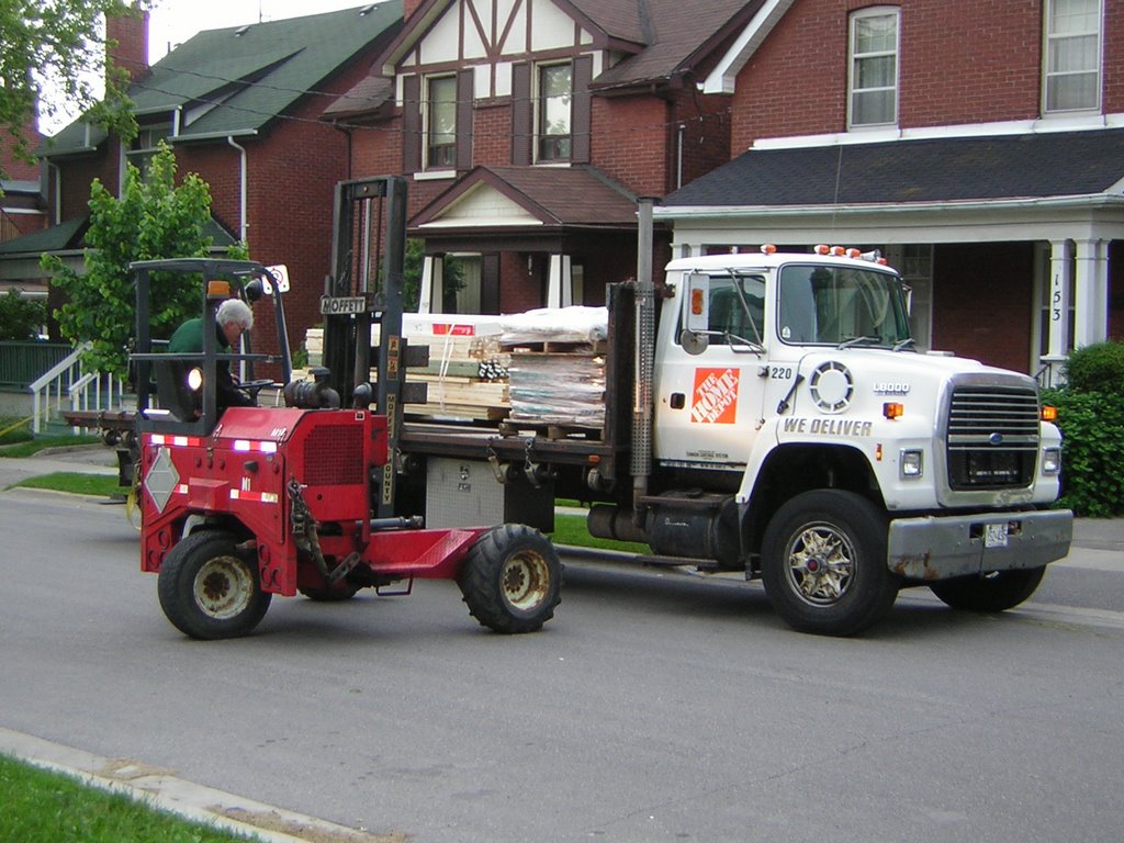
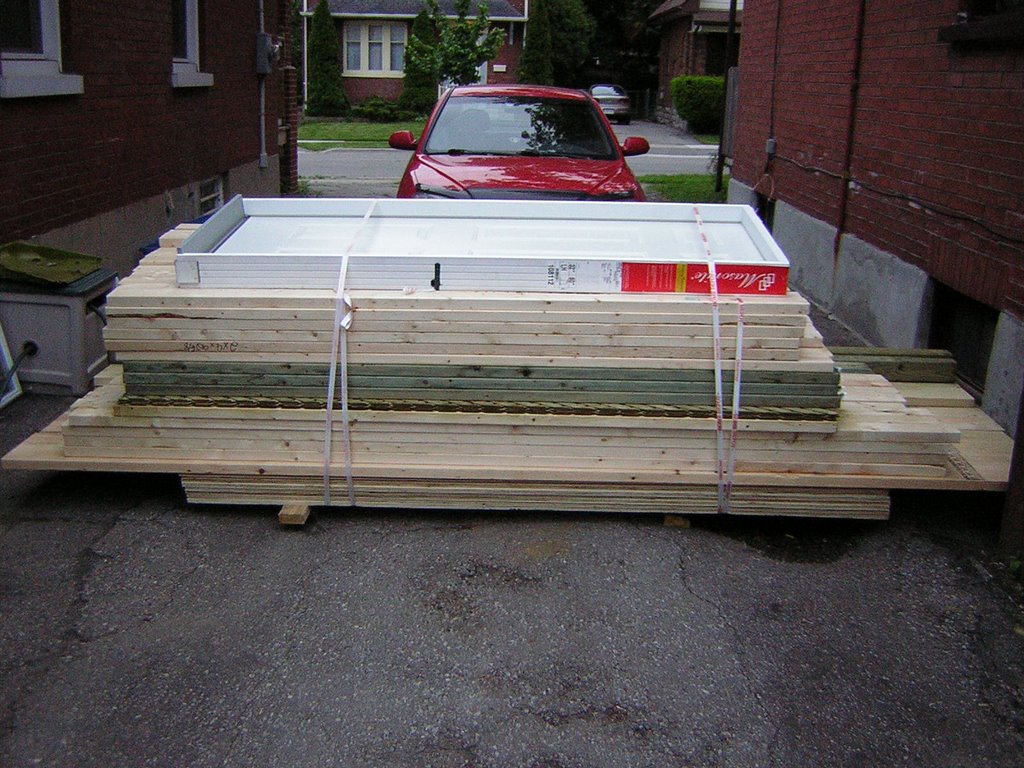
The first stage of the makeover, the delivery of goods, occured today. After a 12 hour delay the Home Depot truck arrived and the material was delivered by forklift where needed. Yes - everything on that truck is for us! The garage door won't be available for a few more weeks. In the next week I will move the remaining vehicles into storage and start on the roof modifications. I will then build the walls, then order a garbage bin to dispose of the walls and scrape down the roof. The fun has just begun!

PS - figure out how the skid of shingles (and the Lemon) got on the other side of the railing and I'll buy you a beer...

The Lime - Front Hitch


Here's another creation I plan on marketing. As soon as we planned to get the van Vanessa and I planned on utilizing a front-mounted bike rack to carry our bikes camping. Some people with front mounted spare tires have spare tire mounted bike racks more commonly seen on SUV's. I would have considered this kind of setup, but since the spare mounts only to the sheet metal of the nose I thought it best not to hang 100+ pounds of bikes on such a contraption. Most bike racks now conveniently connect to trailer hitch receivers, so it made sense to me to fabricate a front-mounted hitch. Naturally I am not the first to do this, but possibly the first to do it this way.

After agonizing over how big the assembly was going to be, and trying to find a suitable mounting surface, it became apparent to me that the front impact beam beneath the bumper is a very solid unit. I decided if I could mount a plate between it and the bumper it would have enough strength to handle the hitch.

As with any project I plan to make more than once, I laid it out in AutoCad before I started - hence the image above. Production went according to plan with the exception of relieving the angle iron with a 1" chamfer where the receiver tube protrudes, in order to provide clearance for the pin or bolt that would hold the rack in place.

The plate is held to the vehicle with eight grade 8.8 8mm x 1.25 bolts and 16 washers. The bolt and washer is "fished" through the access openings on the back of the impact beam with leftover welding wire and electrical tape. The other washer and nut are gingerly threaded and tightened. The holes in the hitch are 3/8 and the hitch is clamped in place to act as a template for drilling the impact beam, also 3/8. The holes are oversized to allow for the bolts and the welding wire, as well as any misalignment in drilling.

The hitch went together easily and with a small modification to the licence plate location and the bottom of the bumper, the receiver now exits about 1/4" below the bumper in a very subtle way. I am quite happy with the look.

I will post some pictures of the finished product soon, once I can put the bikes on and test it out.

Once fully tested I will sell these hitches complete with installation instructions. The price will be $75 US plus shipping. Email me if you are interested.

Thursday, June 08, 2006

The Lime - Front End Repairs - Part 2

Sorry, no pics for this post. I was too busy fixing to snap some shots. I already regret it. The best way to make this post now is to summarize what has now been completed:

TORSION HOUSING PATCHES
-drivers side outer bottom 5" completely removed and refabricated
-drivers side inner, passenger side inner and outer patched where necessary and completely braced from 6" up around the bottom
-all patches made from 18 gauge steel, welded with .023 wire
-holes drilled on lower inner and outer both sides to drain any moisture, small hole drilled on top flange both sides for future rust-proofing endeavours
-both sides painted solely to prevent rust

NEW SHOCKS
-removal of the old was a real issue last week, breaking off the hardened top drivers side mounting bolt
-no combination of hammers, pullers or prybars worked
-used a propane / oxygen torch to heat it red hot, still nothing
-wrecked two titanium drill bits
-bought a $16 cobalt drill bit - worth its weight in gold, which is pretty much what I paid
-drilled out the old bolt which relieved enough pressure to finally knock out the remaining hollow bolt
-12mm bolts are not available in the right length at CTC, HOME DEPOT, or BRAFASCO (same bolt I needed when fixing Bob's Bug's front end!)
-decided due to time constraints to use high grade fine thread 1/2" bolts and nuts, which required the mounts and the new shocks to be reamed to fit
-bought a 1/2" cobalt drill that made short work of this task
-otherwise the new shocks bolted up with no surprises

SWAY BAR
-removal was necessary to access the steering pivot
-old clamps were pretty rotten too
-wire brushed and painted sway bar red
-used new mounting kits from www.cip1.ca which were fine except the mounting bolts provided were too short, had to get two longer 10mm bolts
-otherwise the new sway bar bolted and clamped up nicely with the new rubber bushings - a big improvement in the looks and safety department

STEERING DAMPENER
-this was a simple removal and swap with new
-the old dampener slid from side to side with no resistance whatsoever, meaning it was faulty (and it looked original to the car)
-the new dampener bolted up perfectly and has much more resistance so it should actually do its job

LUBRICATION
-a new 6mm grease nipple was installed into the steering pivot
-all nipples were greased on the front end (5 in total) and it took LOTS of grease likely because of age mostly, but I'm sure the heat from welding didn't do much to preserve the grease that was left inside

THE TEST DRIVE
-once the wheels were torqued back on the van lowered I fired it up and maneuvered out of the work area
-the change was immediately apparent!
-driving along the road the steering is crisp and decisive, a far cry from my last memory
-the new shocks seem to be doing their job, but I can't say yet if they are any better or worse than the originals, I am sure I will notice this on my next big drive
-for the next thousand kilometres I will keep a close eye on the repairs, especially the steering pivot mount
-I can do a test while driving, stopped at a light, to feel for steering freeplay. If I notice any change I will immediately pull over and investigate

Monday, June 05, 2006

The Lime - Front End Repairs Part 1


As mentioned in my last post, we were shocked to find out that despite passing a safety check, the front steering pivot mount was rotten. This pivot mount holds a pin about which a swing lever rotates, transferring the front to back motion of the drag link (connected through the steering box to the steering wheel) to side to side motion needed to move the tie rods and thus the wheels back and forth. Our mount was so bad, in fact, that as we pulled into the driveway after our trip to Michigan, we lost all steering altogether. The first picture above shows this rot.

After looking at the cost of new front axle beams (bare $600+) and used beams ($100US - $500US) and the associated labour involved with removing the current beam I began thinking of other options. Though many disagreed with my plan, John Spironello from Johns Bug Shop - www.johnsbugshop.com told me he used to fabricate new pivot mounts on bus beams all the time, while they were still mounted on the bus! His method seemed to parallel my thoughts, so I ventured forward and created a design in AutoCAD 2000.

In the second picture you can see me cutting out my 1:1 plots of my design. Next I began cutting the parts out using a variety of bimetal hole saws and a 1/16" x 4.5" cut-off wheel in my angle grinder. The next step was to remove the pivot tube from the old sheet metal assembly, clean it, and weld it at the right height onto the top plate of my new pivot mount. Next I squared up the parts using a magnet and tacked the pivot together. I followed this up with a full high-penetration bead (in some cases multiple beads) of weld using .035" wire and a high setting on my MIG machine.

When this was done I realized in removing the pivot tube from the old assembly, I lost the provision for a dust cap on the bottom. So, using more bimetal hole saws, I cut a plate with the exact ID needed to snugly fit a new dust cap and welded it in place, thus completing the new pivot.

In my next post I will show the installation on the vehicle and subsequent installation of new brass bushings, spring washer, pivot pin, thrust washer, top seal, top sealing ring, o-ring, small thrust washer, swing arm, and dust cap.

I plan to market this design when I have proven the concept. Keep checking back for more info!